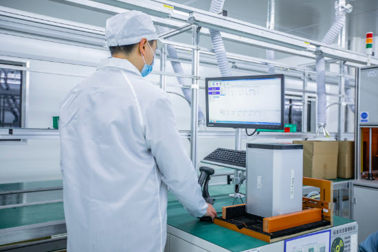
PROCESS ENGINEERING

We believe that a perfect product is made up of millions of perfectly executed details. Kais engineers seize every technical detail as an opportunity to optimize. We are constantly studying and looking for ways to improve our production quality and efficiency, whether it's through in-depth analysis or innovative solutions to challenging procedures.

01.CCD Detection

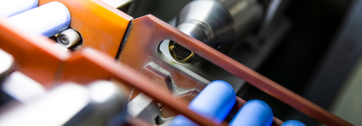
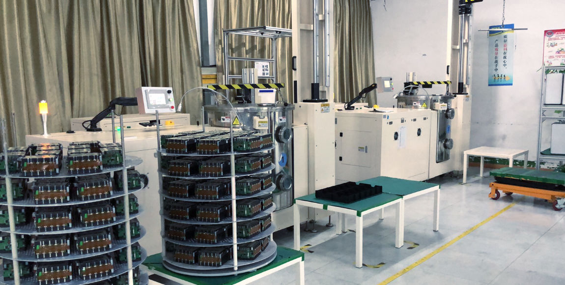
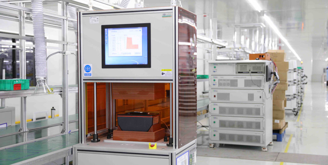
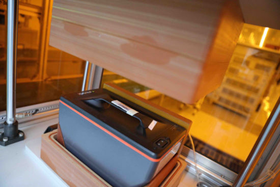
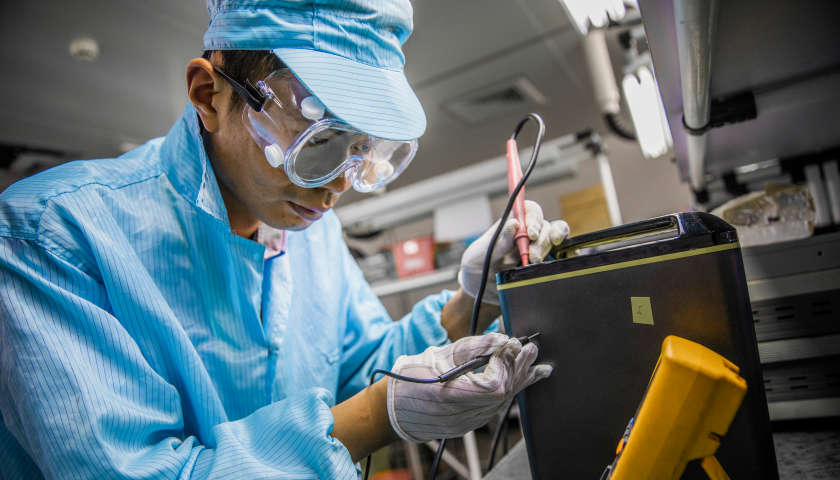
Kais has achieved powerful economies of scale through increasing first pass yield (FPY) rate, our production line is equipped with a best-in-class manufacturing monitor system to catch any faulty process exactly where it happens. One such equipment is the Charge-coupled Device.

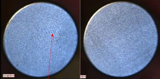
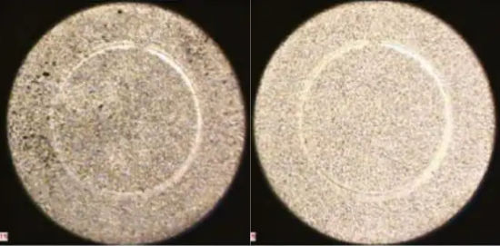
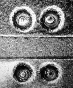
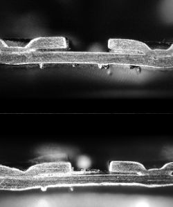
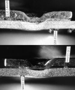
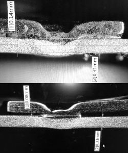
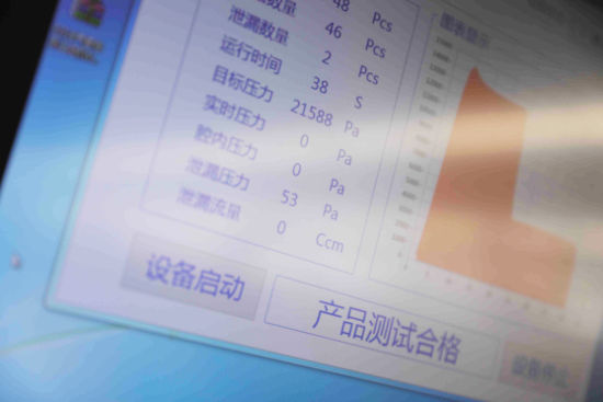
The CCD solder joint detector is automatic equipment for lithium battery processing, which has the functions of automatic positive and negative pole detection, positive and negative solder joint detection, solder joint defect differentiation, automatic discharge, etc.


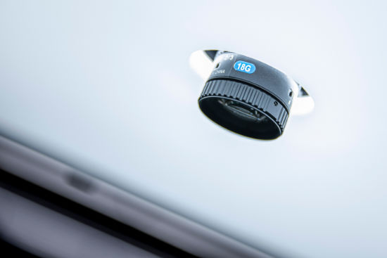
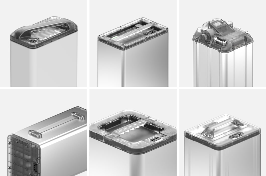
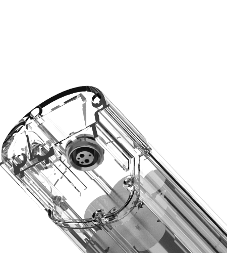
CCD positioning with 0.2mm resolution while insulation paper attachment.


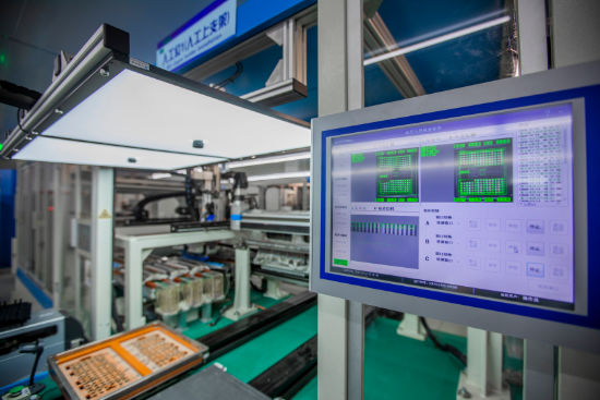
CCD monitoring for cathode/anode polarity during the cell installation process.


02.Plasma Surface Cleaning

Here at Kais, we take into account every minuscule detail that most battery makers overlook, but has a significant impact on the battery performance; one such example is plasma cleaning.

Plasma surface cleaning is a process that uses ionized gas to interact with a substrate to remove contamination and/or modify its surface. Plasma cleaning is a surface modification process and an etching process. Plasma cleansing applications are methods to promote adhesion between two items by decontamination of their interfacing surfaces, generating a modified surface condition, converting to higher surface energy, removing metal oxides by physical and/or chemical interaction.

This is especially important when manufacturing battery packs. A battery pack consists of two or more individual battery cells. The electrical connection between battery cells is typically achieved by a metal tab attached to each cell. Every connection is critical to the overall performance of the finished battery. Organic contaminants such as dirt and fingerprints or the presence of corrosion inhibiting agents like thin film coatings can contribute to low tensile strength joints in welding processes leading to poor adhesion, cracks, and porosity between the materials.

We perform plasma surface cleaning to every cell we process, cleaning the joint interface before welding to help ensure defect-free joints, which result in stronger welds, higher bonding yield, and improved battery performance.


Image of negative can surface with fingerprint (left) and after plasma cleaning (right).


Image of negative can surface with a significant amount of debris (left) and brighter, cleaner surface (right) to achieve stronger performance in pull test.


03.Weld Penetration Depth Analysis

A battery pack is made up of battery cells welded together from terminal to terminal by metal tabs. The penetration depth of welding is a critical factor to ensuring a safe and stable connection in the battery, especially for welding on the negative terminal. If the penetration depth is too light, then the connecting tab may fall off from impact, and if the depth is too deep, then the battery may be damaged in the process, causing an electrolyte leakage.

A simple optical inspection of the surface only provides limited information about the depth of the weld seam, smaller damages to the battery cell can easily escape notice. These small leakages will slowly accumulate and degrade the battery causing battery performance to deteriorate and increase safety risk.

Balancing the welding penetration depth is not an easy task. Kais utilizes many analytical tools to overcome this challenge, performing welding cross-section measurements to measure such items as the fillet welds, throat, leg lengths, and penetration. Our research lab dissects and researches different combinations of battery cells and tab materials from various suppliers, adding that knowledge to our ever-expanding database and using these data as guidance to weld with precision.


Front image of the weld point.


Cross-section image of the weld point.


Image of the melted zone between 0.09mm-0.14mm, 30% of the molten pool depth (acceptable parameter: 15%-50% of the molten pool depth).


Image of the heat-affected zone (HAZ) penetrates the battery cell can (acceptable interval: complete penetration without deformation).


Reference: A study of weld penetration analysis of Tenpower INR18650-32ME

04.Atlas Copco Tightening Technologies

A loose joint in a battery pack may lead to fatal consequences. Both the integrity of the pack structure and the smooth conductivity of current flow are compromised by a loose joint, which causes the contact surface to decrease and electrical resistance to increase, leading to temperature rise and even ignition.

Kais makes sure that all screw threads are fit tight without deformation by using Atlas Copco tightening technique. This is done through two simultaneous loops: each screw joint is installed with precise torque and insertion angle, the toque seating is monitored in real-time and inputted into the seating control model, the model is then adjusted into the seating control strategy, which is applied to install and monitor the subsequent screw joints. Floating screws and striped joints are rejected and logged into our MES for future references.


ILLUSTRATION OF ATLAS COPCO TIGHTENING

05.Insulation Testing


Kais Power is a safety-oriented manufacturer, that’s why a very rigorous testing process is carried out at every stage. To ensure the quality of our insulation resistance testing, we use the Hioki electrical safety testers to test every pack that comes off our production line. The Hioki electrical safety testers are designed for insulation resistance and voltage-withstanding testing of electrical devices and components according to various safety standards. delivering pass/fail assessment in as fast as 50 ms. 25 to 1000 V test voltage with 1 V resolution.


ILLUSTRATION OF INSULATION

06.Parylene Coating


Parylene Coating is the latest revolutionary technology in the field of ingress protection. It allows batteries to achieve IPX8 at the battery module level, meaning that the batteries can achieve full waterproof without the outer casing.

Parylene is a superior barrier layer that provides protection from moisture, corrosion, salt spray, solvents, and airborne contaminants. It is chemically inert, ultra-thin, pinhole-free, and conforms to components evenly and consistently. Combined with its unique molecular-level deposition, this high level of protection is achieved with 10% of the mass than spray or dip coatings.

This technology has seen few uses outside of the medical and aerospace industry due to its intimidating cost. With recent breakthroughs in parylene commercialization, this technology has become much more affordable, and it is quickly gaining popularity in various electronic industries. Today, Kais introduces the Parylene Coating technology to the battery pack industry.


Image of Parylene coating production line with a single batch capacity of 1,800 battery cells.

07.IP Leakage Testing

Impeccable ingress protection starts from a meticulous design, but ultimately it requires consistent and rigorous testing to attain. Here at Kais, our assembly lines are fully integrated with the differential pressure decay leak measurement process, which ensures that every battery pack is tested thoroughly as it rolls off the assembly line.

Differential pressure Decay is the most efficient testing technology for air impermeability. It functions to test the air-tightness of the whole pack as it is being built. The method used is based on the measurement of a small variation or drop in differential pressure between the test and reference parts when both are filled to an identical pressure. The process is monitored and all test results are uploaded to MES as reference for our process engineer to optimize.


IP leakage testing fully integrated into the production line.


Image of an E-motorcycle battery pack in the differential pressure decay leak process.