Electrical Engineering

Our proud engineering-driven culture is what sets us apart from our competitors in the industry. Here at Kais, every engineer understands and respects the potency of lithium batteries. We believe that safety should never be a choice, but we understand that in real-life situations, safety is often weighed against cost. Kais aims to eliminate that choice entirely and enable our customers to have both at the same time.

THE FUNCTIONAL SAFETY OF BMS

the functional safety of the BMS is the last line of defense

Safety is always the primary concern when it comes to batteries. Any small flaws in design or execution may compromise the battery and lead to a dire consequences. Designing a safe battery demands an all-out effort from every process, but the functional safety of the BMS is the last line of defense.

The functional safety of Kais BMS is achieved through four interlocking puzzles, a methodically designed system with multiple layers of logic components to hold each other in check. Secondary and tertiary fail-safe mechanisms to prevent and eliminate incident escalation, thoughtfully placed sensors to monitor the real-time status of the battery, and scrupulously tested components sourced from top tier suppliers.



FUNCTIONAL SAFETY STANDARDS

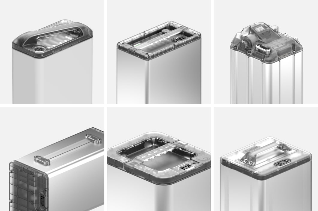
E-Mobility standards such as UL 2849 and EN 15149 have outlined high standards for functional safety, including specific requirements for the battery components, dictating the batteries to pass various standards as prerequisites. Kais has developed our own BMS products that satisfy safety standards such as EN ISO 13849-1: 2015 (PLr c), EN 15194:2017 clause 4.3.22, etc.


Short-circuit protection

a critical function that people’s lives and property depends on

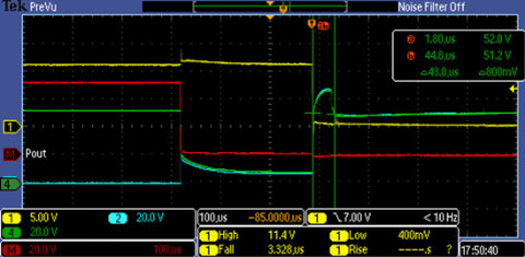
If a short circuit occurs while the battery is discharging, the protection circuit will be activated to counteract it. The protection circuit is made up of two components, the current monitoring circuit and the discharging control circuit. The monitoring circuit monitors the discharging current in real-time; when it detects the current reaching higher than a pre-set range, the short circuit protection program kicks in and shuts off the discharging circuit.


TESTING PROCEDURES


  1. The battery begins discharging.
  2. The Power relay is connected to force a short circuit.
  3. The current monitoring circuit detects the sudden increase in current has exceeded the protection range and activates the short-circuit protection program.
  4. The discharging MOS tube is closed off.
  5. The power is shut down immediately to protect user safety.

PRE-CHARGing CIRCUIT

Pre-charging circuits extend product life and reduce the safety risk

Due to the large capacitance on the load side of the PACK when discharging, it is prone to sparking when the battery PACK is installed. The sparking may damage the PACK and the connector on the body, reduce the contact performance of the connector, and when there is a large current discharge for a long duration, the internal temperature will increase and potentially affect the safety of the users. Therefore, it is critical to add a pre-charging circuit for charging the capacitor to avoid ignition.


PRE-CHARGING PROCEDURES


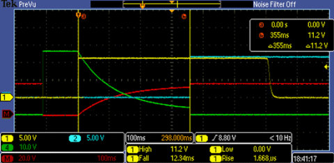
This is done by reducing the impulse current when the power is turned on by increasing the pre-charging circuit. Before the main discharge circuit is opened, a small current discharge circuit is opened first, and the small current discharge is used to charge the large capacitor on the load side. It will be charged to 90% of the capacitor capacity. Close the main discharge circuit to start high current discharge. The whole circuit can be regarded as an RC charging circuit, the circuit structure is as follows.


PARALLEL BATTERY SOLUTION
Extended run time
& better acceleration performance

For some e-mobility applications, such as sharing or delivery vehicles, one battery is simply not enough. In those cases, two or more battery packs are needed to ensure product performance matches the customer needs. Putting more than two battery packs in parallel is more complicated than it seems. Special control mechanisms need to be designed to ensure that the two batteries in parallel won't reverse-charge and discharge into each other.

For your parallel battery pack solution, whether you need a master-slave parallel or auto-parallel solution, Kais has the right solution for you.


MODEL-BASED SOC AND SOH ESTIMATION
WITH 3% VARIATION

The State-Of-Charge (SOC) is one of the most important parameters in a Battery Management System. But SOC cannot be measured directly, so it is obtained through a series of complex calculations, factoring in variables including operating environment, self-discharge, state of aging, current density, etc. Thus online SOC calculation has always been a challenging and hotly debated topic.

We at Kais are constantly testing and evaluating new and existing calculation methods in the industry, through hypothesis and comparison using vast amounts of big data available to us. We were able to determine and document the theoretical and practical advantages/disadvantages of each method. For our SOC estimation algorithm, Kais utilizes data-driven methods combining dynamic and static adjustment techniques to achieve 3% estimation variation.

The State-Of-Health (SOH) of a battery is useful in assessing the condition and the life-cycle stage of a battery. Kais leverages our precision SOC estimation and our in-depth battery cell knowledge to get an accurate estimation of the SOH. This is done through careful modeling using historical testing data of both the cells and the batteries.


OTA SOLUTION

AS A PLATFORM, NOT A PRODUCT

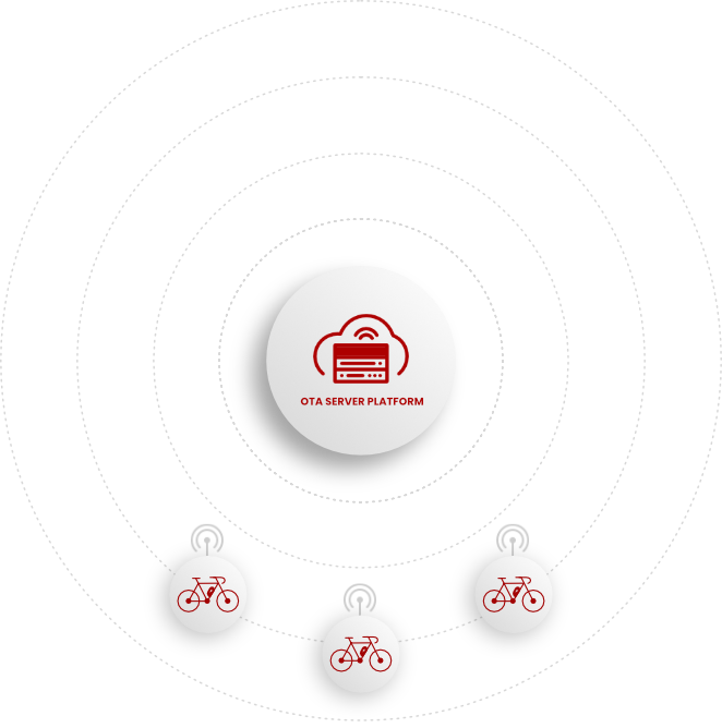
Kais has developed and incorporated various connectivity features in our batteries tailor-made to support our client in this new era, including OTA update, Kais Diagnostics™, Preventive maintenance, and Fleet management tools.

Kais OTA update feature allows our clients to update battery software over the internet, providing flexibility in after-sale support and new feature upgrade, greatly enhancing user experience.

Kais Diagnostics™ is a diagnostics tool used to keep track of battery health and usage data. Its primary purpose is to perform preliminary troubleshooting and assist with aftersale services. Still, it is also useful to help our clients to learn about their customer’s user habits and aid them in future product development.

To assist mobility sharing and delivery operators, Kais battery products are designed to support preventive maintenance and fleet management functions. The operators will gain access to real-time information regarding the status and health of the batteries. This information will allow them to optimize their fleet maintenance schedule and charging time plan, smoothing out their fleet operation.


DOWNLOAD
KAIS DIAGNOSTICS™

Kais Diagnostics is an in-house developed battery pack monitor and diagnostics software that supports all battery packs integrated with the Kais firmware framework.


Learn More